The wiper motor is a crucial component in vehicles, responsible for moving the windshield wipers back and forth to maintain clear visibility during adverse weather conditions. One important feature of a wiper motor is its ability to operate at different speeds, allowing drivers to adjust the wiping rate depending on the intensity of rain or snow. Understanding how the speed of a wiper motor is regulated involves looking at the motor’s design, electrical control systems, and sometimes mechanical components.
Most conventional wiper motors use a simple DC motor design that allows speed adjustment through changes in the voltage or current supplied. The speed of the motor is directly related to the voltage applied across its terminals—higher voltage generally results in a higher rotation speed. To enable multiple speed settings, the motor is often connected to a control circuit that can switch between different voltages or resistance values, effectively changing the motor’s speed. This approach is commonly used in basic wiper systems where a few speed options, such as low, medium, and high, are sufficient.
In more advanced systems, speed regulation is achieved using pulse-width modulation (PWM) technology. PWM controls the effective power delivered to the wiper motor by rapidly switching the power supply on and off at a certain frequency and varying the duty cycle, which is the proportion of time the power is “on.” By adjusting the duty cycle, the motor receives different average voltages, allowing precise control over its speed without causing excessive heat or energy loss. PWM offers smoother and more efficient speed control compared to traditional resistor-based methods.
Some modern vehicles integrate the wiper motor control within an electronic control unit (ECU), which manages not only speed but also intermittent wiping intervals, automatic rain-sensing adjustments, and the parking position of the wipers. The ECU uses sensor inputs and programmed logic to determine the ideal motor speed, optimizing wiper performance for varying weather conditions. This level of control enhances driver convenience and safety by automatically adapting the wiping speed as needed.
Mechanical factors also influence the perceived speed of the wiper blades. The linkage and gear system connected to the wiper motor often includes mechanisms to convert the motor’s rotary motion into the back-and-forth sweeping motion of the blades. Gear ratios within this system affect the final speed and torque delivered to the wiper arms, meaning that the motor speed alone does not fully determine the wiping speed. Properly designed linkages ensure efficient operation and prevent overloading the motor at higher speeds.
In terms of user control, the wiper switch inside the vehicle cabin typically allows selection of different speed modes. This switch sends signals to the motor control circuitry or ECU to adjust the power supplied accordingly. Some switches also enable an intermittent mode, where the motor runs at intervals controlled by a timer or sensor, providing further customization to the wiping speed.
Overall, the speed adjustment of a wiper motor combines electrical control methods, mechanical design, and sometimes sophisticated electronic systems. Whether through voltage regulation, PWM, or integrated ECU management, these technologies ensure the wiper motor operates effectively across different speeds, enhancing visibility and safety during adverse weather.
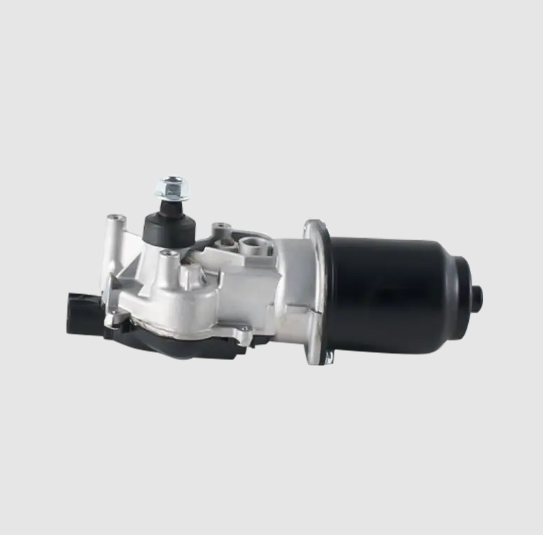
Wiper Motor Power Voltage:12V DC, 35W
No-load Current Low speed: ≦1.5A, high speed ≦: 2.0A
No-load Speed Low speed: 37- 42 rpm, high speed: 55- 62 rpm
Braking Current Low speed: ≦19A, high speed ≦: 25A
Braking Torque Low speed: ≧27Nm, high speed : ≧23Nm
Motor Noise: ≦55dB